 by Chris Crane/photos by the author
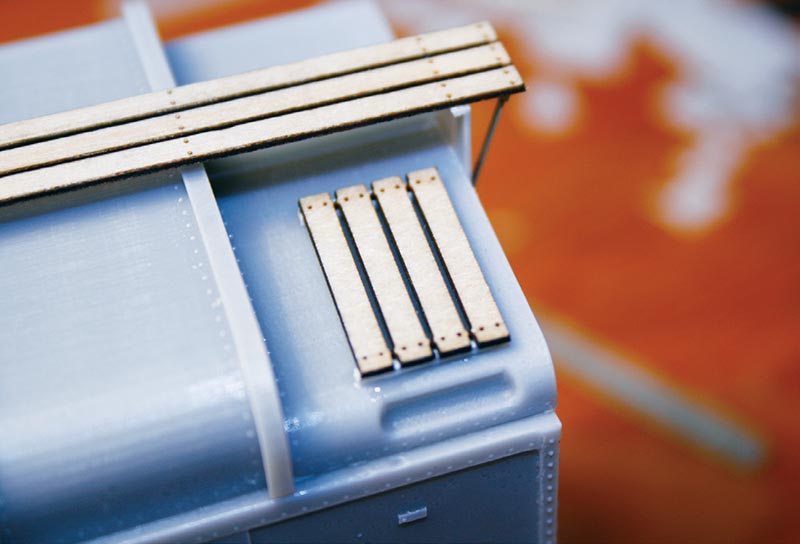
This article describes in detail the process involved in building the Yarmouth Model Works kit of Pennsylvania Railroad’s unique X31f “turtle roof” boxcar. The kit includes mostly detailed instructions and this article follows Yarmouth’s suggested procedure. There are exceptions which I will point out. The kit includes the assembled body, floor, and detail castings, several sealed bags of detailing parts, various sizes of wire, and laser-cut wood roof-walk pieces.
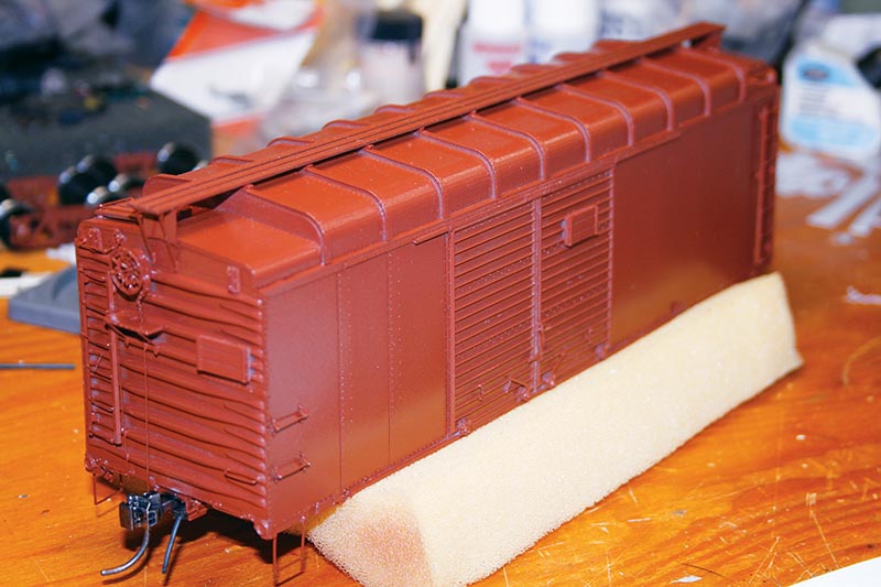
The 3-D-printed roof contains slight ripples in the sheet metal surfaces from the printing process. I used a foam emery stick to knock down the ripples, taking care not to hit the rivet detail at the roof ribs. You could also cover that detail with tape to protect it while sanding. Once that exercise was completed, I washed the body pieces with mild soap and water to remove residual mold release. There are casting vents on the interior of the body at the floor level that are to be removed so the floor fits properly. I neglected to photograph that detail. After minor filing, the floor test fit into the body perfectly.

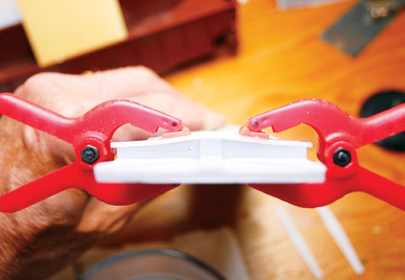
The instructions state to remove a couple of cast details from the floor underbody. They were cast for the brake reservoir for the original X31 kit. This car version orients the reservoir differently. Drill the cross-bearers and bolsters for the train line. Cut the bolster and cross-bearer cover plates from the casting. I used small sharp scissors and a knife to do this. Glue and clamp the cover plates to their respective locations. The bolster cover is a compound curve, with the pieces clamped while the glue was curing. I should point out I used both thick and medium viscosity CA for affixing all resin pieces.
I drilled and tapped the bolsters for a 3mm shouldered machine screw. This is a fairly common size for both Rich Yoder (RY) and Precision Scale trucks. This model will eventually have RY trucks under it. At this point I deviated from the instructions and decided to build out the entire underbody detail first, prior to attaching the floor to the model body. Doing so made this installation work easier.

For the underbody, begin by identifying the appropriate package containing the brake details. The cylinder, air tank, and triple valve are all made up of multiple parts. The instructions illustrate this for you. Take your time to get them correct. Run the train line using the provided 0.033” wire. Get the train line end mounts from the metal fret and mount them into place. The mounts for the air tank and triple valve also come from the etched metal fret. The instructions have a photo identifying each component on the fret. Bend each mount to shape. This is a good time to pre-drill each brake component to receive the appropriately sized wire before mounting them. The kit contains cast plastic rod clevis ends, a very neat detail. Drill and glue each to accept brake rigging rods as you progress…


