
 By Martin Brechbiel/photos by the author
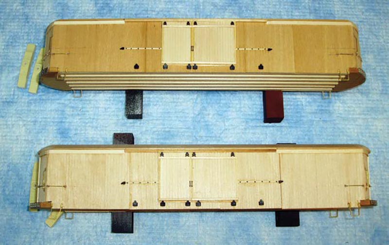
Well, it’s been a long time coming, but we’re starting to get to where an end to this build can be seen – applying details to these “naked” cars! From here on, I’m effectively abandoning the LaBelle instructions and looking exclusively at the set of plans published in Model Railroader to get something that looks acceptable without encountering excess neuroses.
The LaBelle kit supplies track spikes for door hardware; we can do a bit better. Camel door hardware is available from Chooch (#215) and you’ll need at least two sets per car (four doors per car). I applied door supports, two close to the bottom corners of each door and then two more 4’ and 5’ out, respectively, to support opening the two different width doors. A bit of CA on these parts with some weight secures them and the doors as well. At the top of each door there needs to be a hanger in each corner. I removed the tops of these parts (scalpel) to simulate their being up under the door trim on their runners and secured them with cyanoacrylate (CA) adhesive.
The little end stop castings that go at the ends of those HO scale 1×4 strips that run behind the door were added at the end of the prior column. Another little detail to add are the bolt heads for securing those same HO 1×4 strips. I used Grandt Line #101 nut-bolt-washer castings, drilling holes on 1-foot spacing between each door and stop, and inserted them with a little CA. Then I went back and added strips of O scale 1×3 to the doors just above and below the door supports and hangers (Photo 1). Also in the Chooch parts are door handles that were secured with a very small dab of CA. One could add more parts, but let’s reach a representational stopping point. On to stirrup steps and grab irons!
Applying stirrup steps at each corner on the sides used up a set (Precision Scale #40532) from my parts bin. You could also just make your own from some flat brass stock from Detail Associates. All of the grab irons were made from 0.028” brass wire (Detail Associates). There are two on 1 each side that are 2-foot long with the one end anchored about a board width in
from the end of the side and 2’ up from the top of the end platform. Make all four at the same time to get them identical in length. I use a hemostat to insert these.
Drill the end hole first (#70 drill), use that hole and the wire grab iron to locate and drill the other hole, dip the ends of the wire in Walthers Goo, and insert into the holes to get a reasonable exposure of the grab iron. While the Goo is fresh, I lopped off the heads of some Grandt Line #23 NBW castings and applied those adjacent to the grab iron wire.
There are four more grab irons on each end: two vertical (2.5-foot long) and two horizontal (3-foot long). Again, make all that you need in advance. The horizontal grabs have to account for the curved geometry of the ends. They are two feet up from the top of the end platform and are centered between the end doorframe and the corner of the car. The bottoms of the vertical grabs are just above the horizontal grabs. These were applied just like the ones on the sides and dressed up with the Grandt Line #23 NBW castings, too. One last detail to apply is the anticlimbers on those curved ends! These are soft white metal castings from Q-Car (CS334) and are easily shaped to the contour. They are a tad long and need to be trimmed with nippers to length. I secure them with a film of Goo on the end grain surface of the wood and CA on the metal surface. This is pretty close to contact cement, so get this right the first time! With the exception of one detail area, that pretty much addresses the topside details; let’s get started on the underbody!
So, bolsters, supports for queen posts, and a “K” brake casting, and then truss rods and turnbuckles are what get put under these cars. I use my own resin cast bolsters cut down to the proper width, drilled and tapped for a 4-40 screw. These get located centered 4½’ in from the square end of the under-body. I use a bit of Goo on the wood and some CA on the resin. You can get car bolsters from Q-Car, or cut down some from Precision Scale, or make your own from wood, or you can nag me for some. The supports for the queen posts in the MR plans show “I” beams, so styrene “I” beams (5/32”, Evergreen) were cut to width and centered 17¼’ in from the square end of the underbody and secured with CA.
We’re going to have to stop here since how the truss rod system was assembled exceeds both allotted space & time (and possibly tests one’s level of excessive); so that’s a tale for when we return.