
 By Bob Glorioso/photos by the author
In the mountain divisions of most major railroads, wooden trestles predominated at the turn of the century. Building materials were usually cheap and readily available, and construction proceeded quickly. But these wooden trestles were prone to fire and decay. Between 1911 and 1914, the Rocky Mountain Division of Chicago, Milwaukee, St. Paul & Pacific (“The Milwaukee Road”) filled in some wooden trestles with rock and dirt and replaced others with steel trestles. After 1910, steel trestles alone were built for new trackage. The steel trestles were of a lattice truss design and this presents some modeling challenges in O scale. There is a 3-D-printed option, but no O scale styrene girders. Fortunately, Central Valley Model Works (CVMW) Heavy Duty HO Laced Girders scale well to 1:48 modeling.
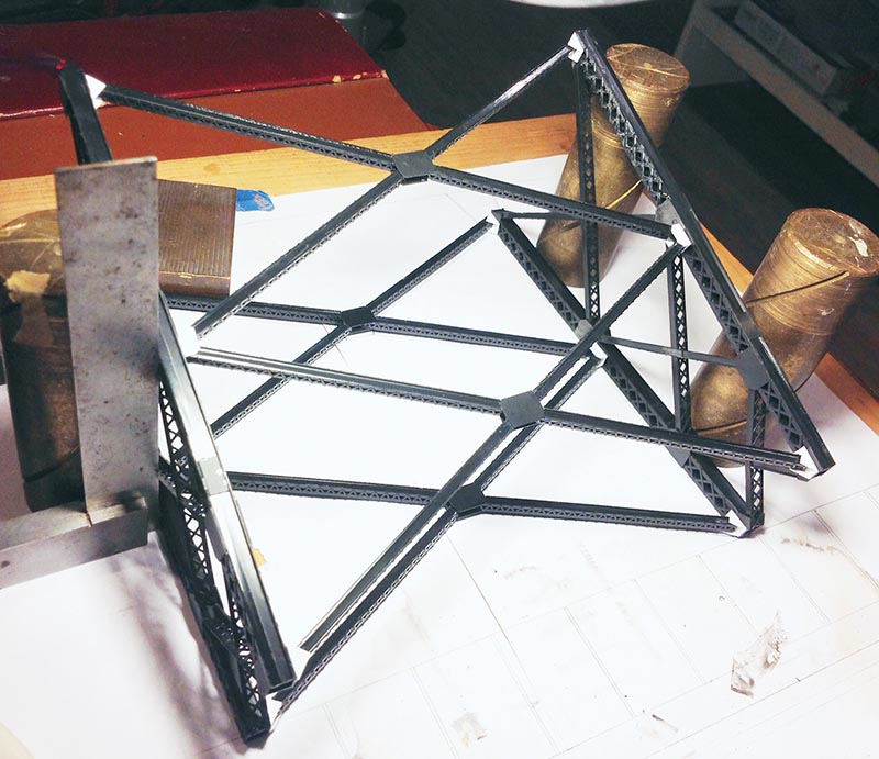
Being a Milwaukee Road modeler, I wanted to model one of these massive steel trestles. I ended up with a plan for a 10’ curved trestle. Like most railroads, CMStP&P built four-leg towers supporting deck plate girders and used two-leg towers and concrete arches at either end. The towers rested on concrete footers. The decks were either standard wood bridge timbers or a formed concrete apron.
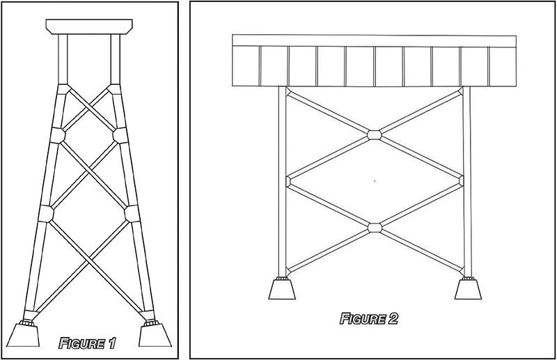
I blew the dust off my drafting board and T-square and drew full-size front and side elevation templates for the towers (Figures 1, 2). I did eventually redraw the templates for this article using a CAD program. When you print the templates, you should size them to 11 3/4” from the bottom of the footers to the top of the rail head. If you require taller towers, simply extend the verticals and add more cross braces. Shorter towers can be made by shortening the verticals and eliminating or relocating the cross braces.
To construct the towers, I used components from CVMW no. 19005 Heavy Duty HO Laced Girders and No. 19025 Original Classic HO Bridge Girders. The smallest girders in the No. 19025 set are not used. Two complete towers require two no. 19005 sets and one no. 19025 set. In the no. 19005 sets, ignore the instructions about making A and B girder styles. We are only using the laced components to make B-style girders. I used a large-handled hobby knife with a no. 19 blade for cutting the styrene girder pieces.
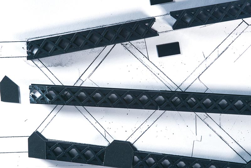
After cutting the large girder pieces off the sprues, make a square cut on the solid girder portions to even the ends. I made these cuts a little long, and then shaved off the extra material in a few passes to get a nice square cut. I used this technique effectively throughout the construction of the towers. If you try to make a single cut, the blade may wander.
After I had a good collection of large girder pieces, I brushed methyl ethyl ketone (MEK) solvent cement on the solid girder edge of the two pieces, then assembled and clamped them with clothespins. You need to work fast because the MEK evaporates quickly. It also dries quickly, which speeds construction…